
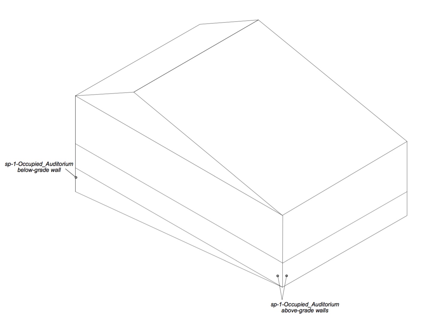
This test can be explained first using axonometric view in Figure 1. It is a large space that consists of a sloped slab on grade and an unusual roof geometry.
It has been revealed that many tools have poor volume calculators and also fail to capture slab on grade elements when the floor is sloped. This test is particularly testing to make sure that when the tool exports to gbXML the floor area for the slab on grade is accounted, and also that the volume is properly calculated within a reasonable tolerance. Note that part of the walls are below grade. These walls have been drawn separately from the above grade walls and called out explicitly in this test. It is expected that this explicit declaration can be captured by the BIM tool. It is not expected that the below-grade walls will be created on export automatically if the user only draws a single wall.
The test geometry consists of a single volume broken into three separate zones (shown in Figure 3), as might be typical of a large single volume space such as an auditorium where the space has been split up for load calculation purposes. Note that Openings of surfaceType Air have been added between sp-1-Occupied_Auditorium and sp-2-Unoccupied_Auditorium and sp-2-Unoccupied_Auditorium and sp-3-Roof_Void, respectively. It is expected that the user has defined something indicating that the volume is open, but that a zone boundary should exist. There are several mechanisms available to do this in CAD or BIM tools. When translated to gbXML, it is expected that the interface of these space boundaries consist of surfaces of type ceiling/interior floor (same thing in gbXML) with an Opening of type Air. It is very important that the space names in your certification file must adhere to the naming convention shown in Figures 1, 2, and 3. If the spaces are not named appropriately, then the validator software will not be able to achieve a Passing Score.
The remaining figures show actual coordinates and dimensions, where the dimensions are drawn at the centerline of the surface, per gbXML convention. Dimensions in the east-west direction are the X-dimension, and in the north-south are the Y-dimension. Z is in the final direction (up and down).
Figure 1
Axonometric View
Figure 2
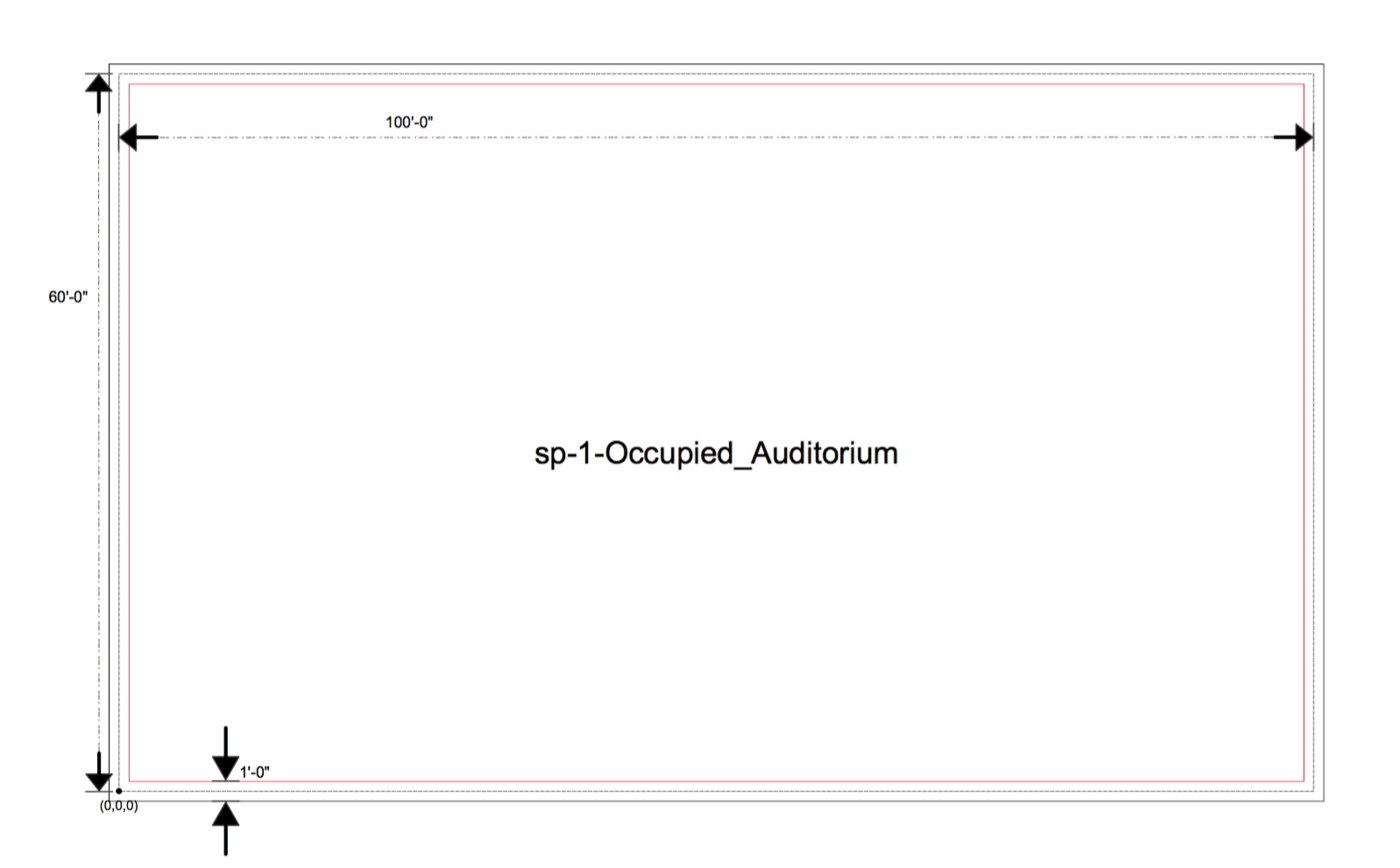
1st Floor Plan View
Figure 3
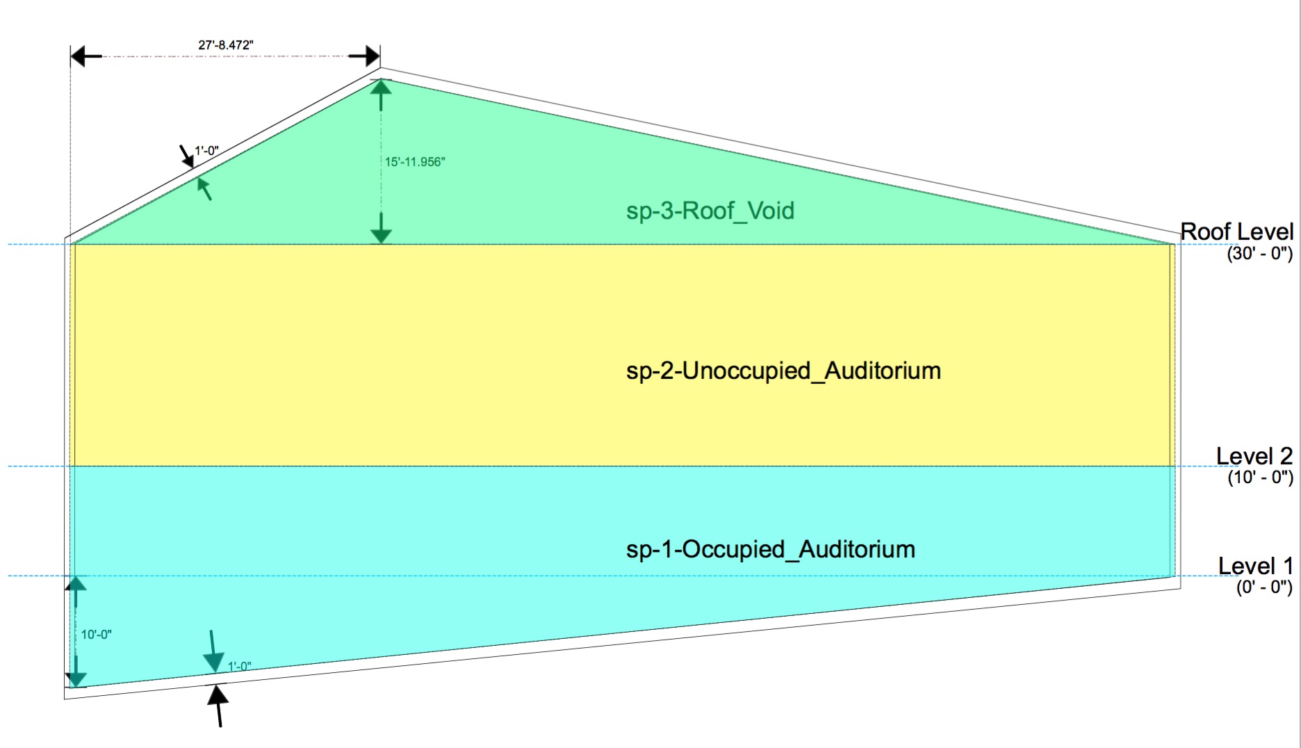
Section Looking North
Figure 2 shows a plan view of the first floor, at a height of 3’ above height z=0. Since all of the coordinates for each zone are the same (with the exception of the z-height) this figure can be used in conjunction with Figure 3 to deduce the dimensions of each space.
Figure 3 shows a section cut through the four single height spaces, where the section cut positions the user at the southern side of the building looking north. The cut takes place at y=30’.
Using these three images, it should be possible to reconstruct this test case in the vendor tool of choice and submit this test case to gbXML for validation towards Level 1 or 2 certification.
Click
here for the test case PDF document.